 Tweet
Tweet
As my first ever modding tutorial that i make i am please to present
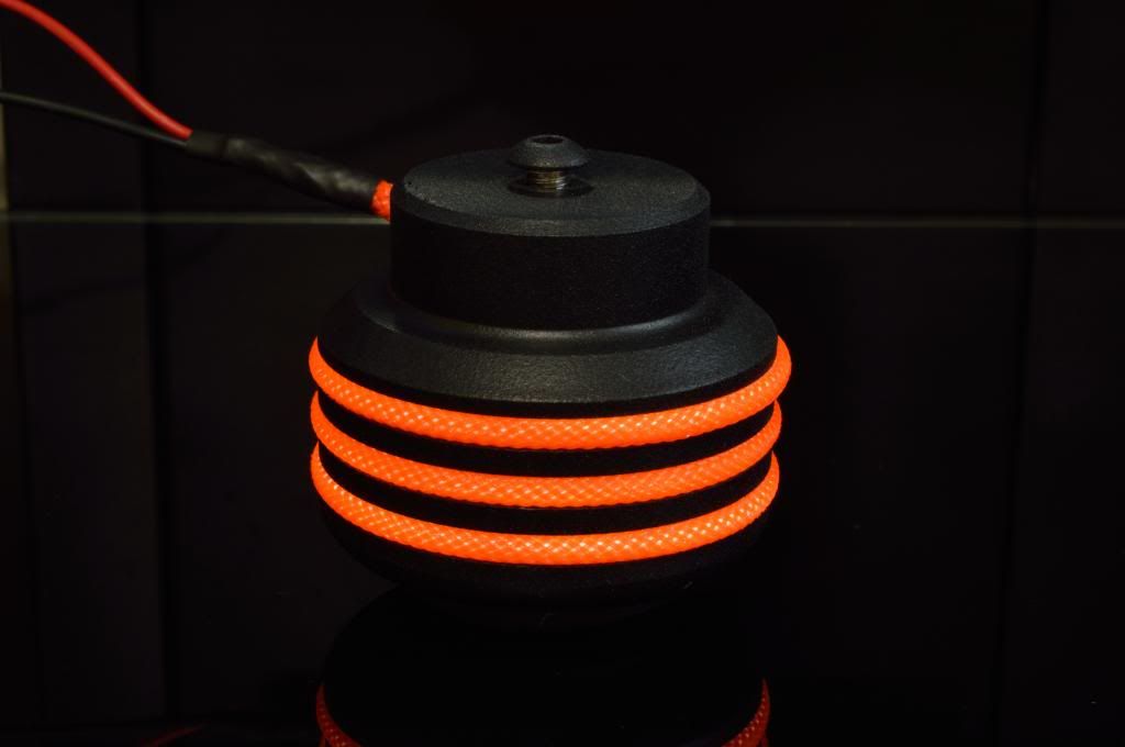
Bladepcmods barrel Case feet with sleeved lights.
what you will need
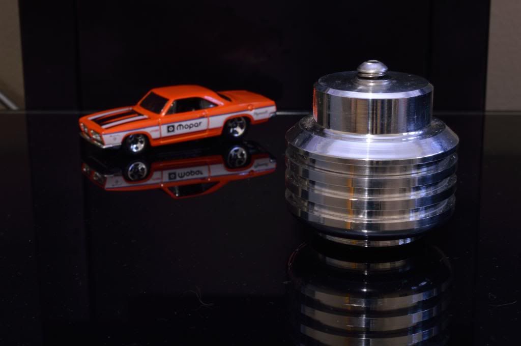
Bladepcmods barrel Case feet
EL Lamp Wire (flex neon)

inverter to convert the 12V voltage from your power supply to the 120V you will need to power the lights (if you buy one for a car on ebay it may already come with this inverter)
wire stripper
wire cutter
solder gun
solder
heat shrink 1/8"
metal crimp and crimper
exacto knife
glue
scissor
2mm(1/8") sleeve. I used darkside sleeve's from dazmode.com they are easy to work with and they look awesome
before we start, I will show you a diagram of how the EL light wire (flex neon) is made and will be making reference to it as we go

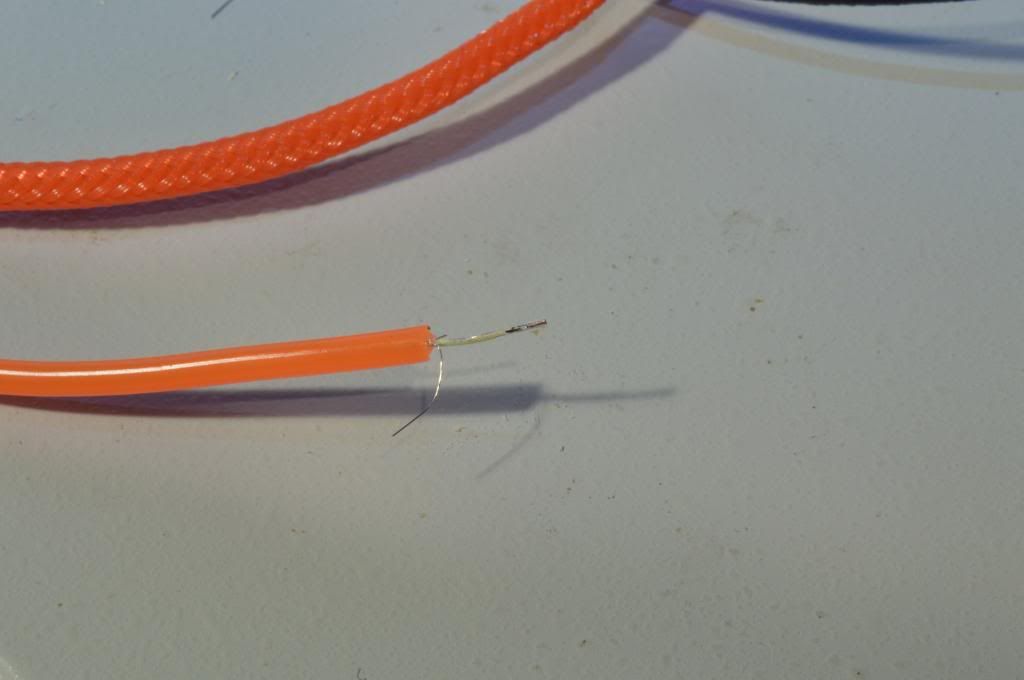
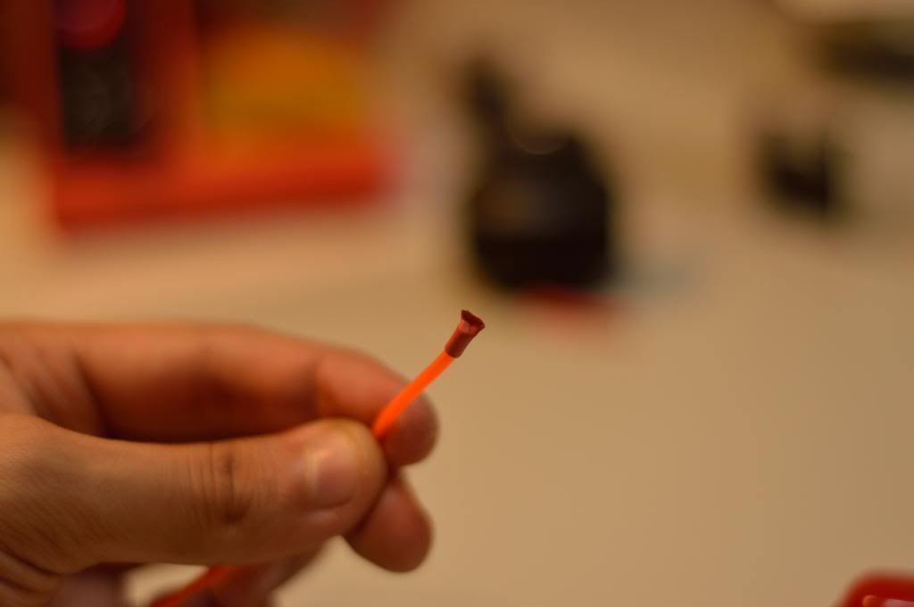
First, you will have to strip the EL light much like you would a wire to remove the insulation. As you can see from the picture below, there is a VERY fine copper wire. The EL wire is composed of two copper conductors on the version of the EL light wire feature in the photo and you will have to be careful when striping the wire not to accidently remove them from the light. I found that the doing so with the 18AWG slot you will obtain the best result, although not always perfect
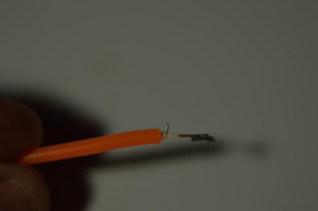
Unfortunately it can accidently happen that the fine copper wire is removed or even that the clear protective sleeve wasn't completely removed. If the clear protective sleeve wasn't removed, you will then need to use the exacto knife to carefully remove the protective sleeve to access the copper wire. Be careful not to cut the copper wire or remove the phosphor coating on the copper core in the process.
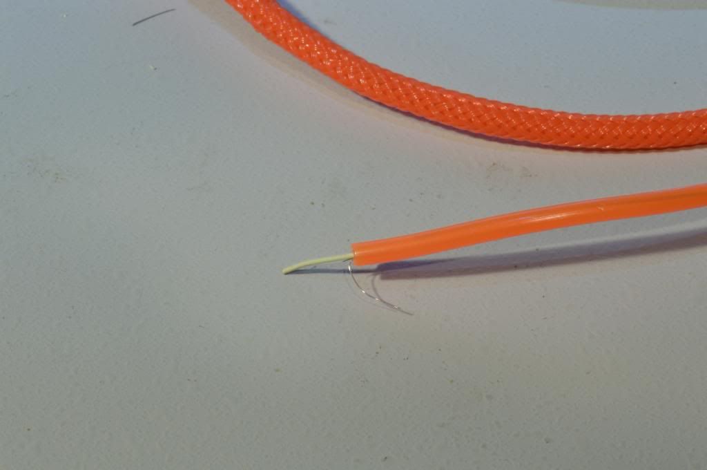
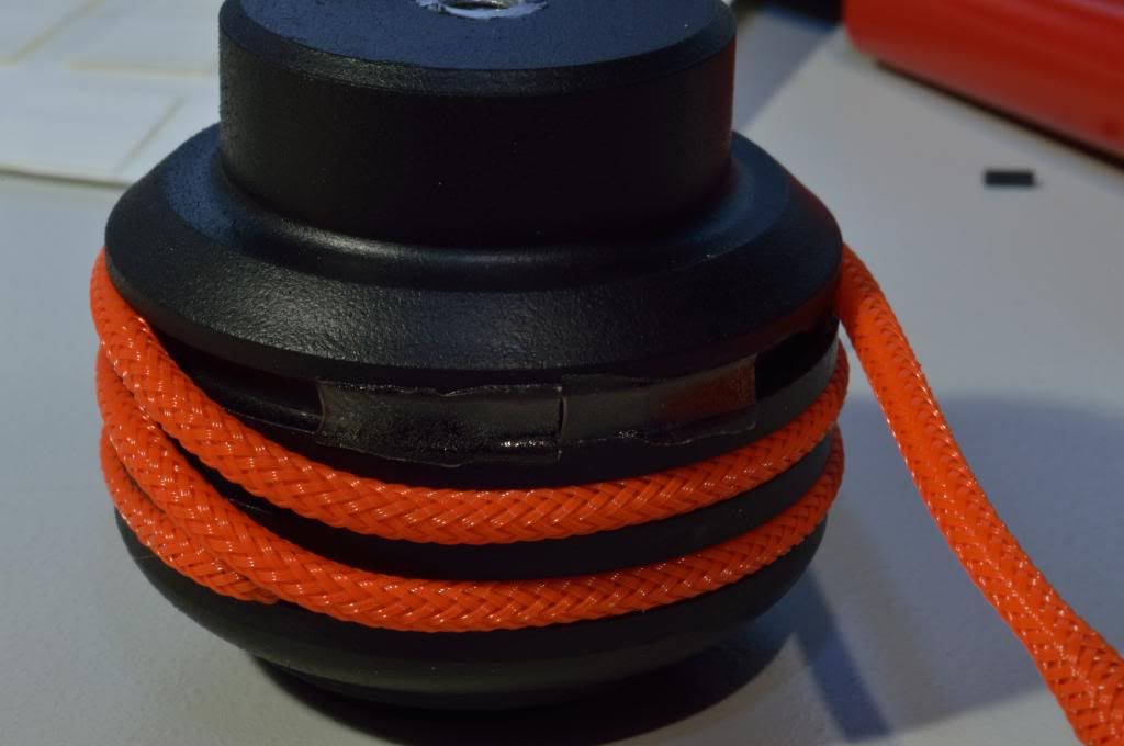
In the next step you will need to cut to length the EL wire as required to go around the feet. The bladepcmods feet size I have required 20" but they do make different size of feet, you can do so by rolling it around the feet as shown below. I recommend that you cut an extra inch just in case (you can always cut it to exact length later). Make sure the wire is nice and tight around the feet.

Once you have completed the steps above you should be presented with the result above.
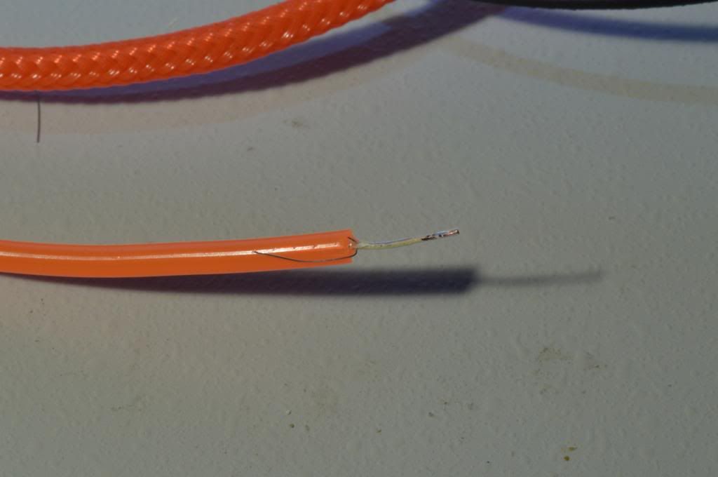
The next step will be to remove the phosphor coating from the end of the copper core so you can properly solder on to the copper core and ensure good contact. You can use the exacto knife or anything that will scratch it off.
Then bend the copper wire back on the top of the colored PVC sleeve as shown below.
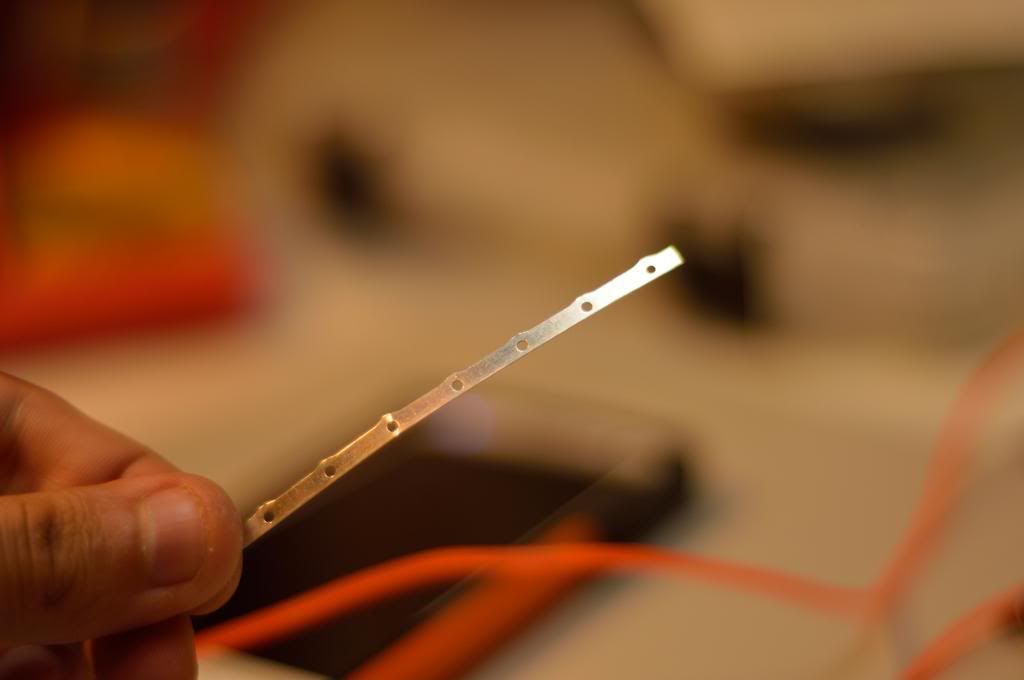
At this point I had to prepare the crimper to attach the other feed, I have recycled the metal parts that my ATX pins are attached to when they are sent to me.
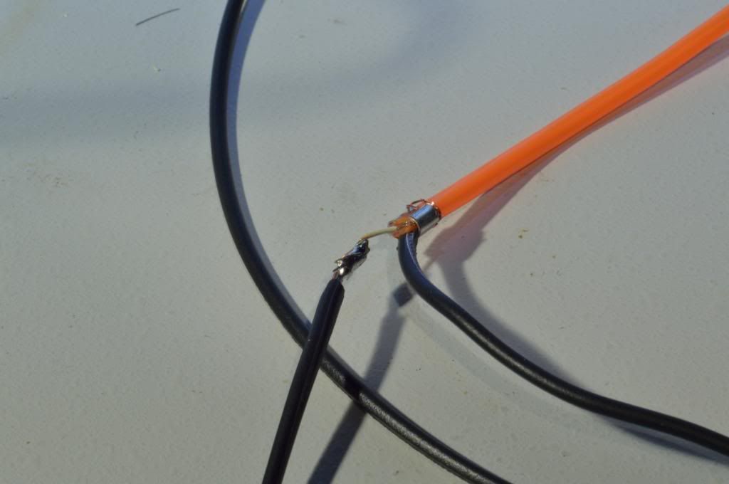
You will then need to sit the wire's core onto that colored sleeve and make sure it makes proper contact with the copper wire to transmit the current and then crimp the wire to the EL light wire while always staying on top of the colored sleeve, it is imperative that you do all this over the colored sleeve to avoid any shorts between the copper wire and the copper core.
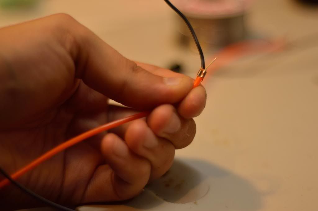
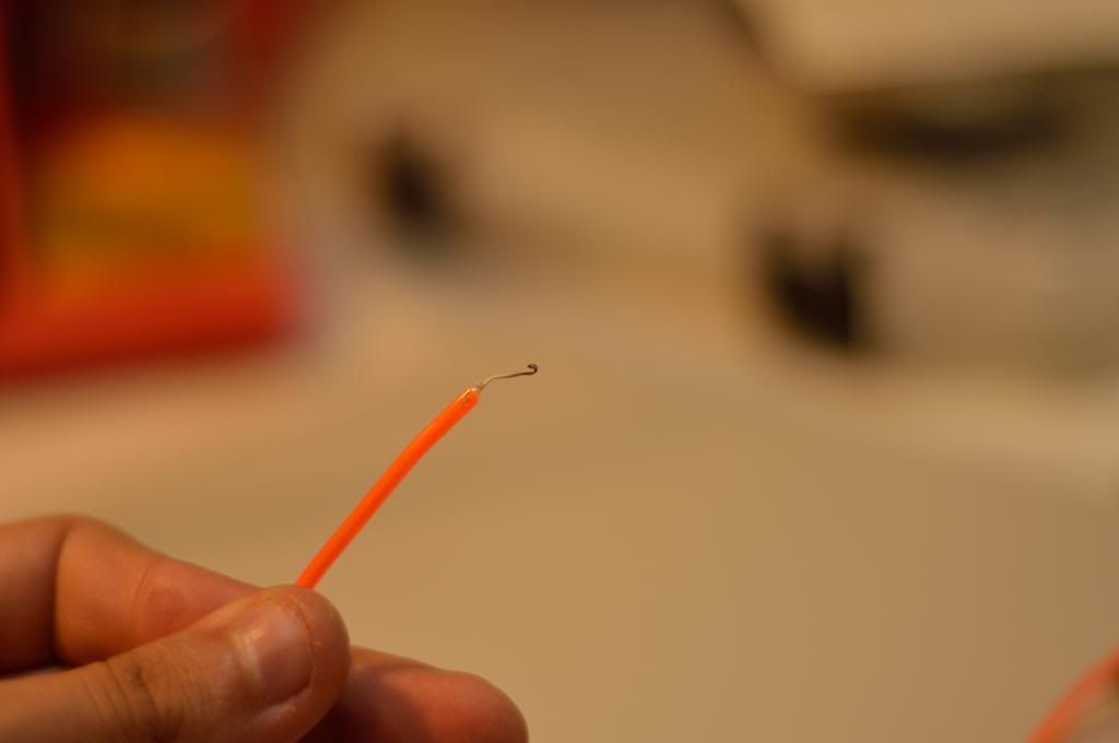
The next step will then be to solder the copper core to a new wire. I found that the solder I had didn't stick well to the core so I made a hook with the core to help set the wire on it to solder and for extra strength.
Then you will have to put a heat shrink over the copper core and the EL light wire attached together in order to help avoid any possible short.
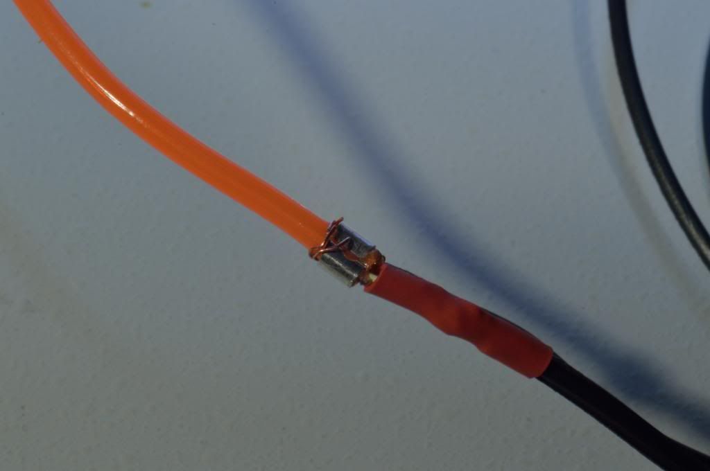
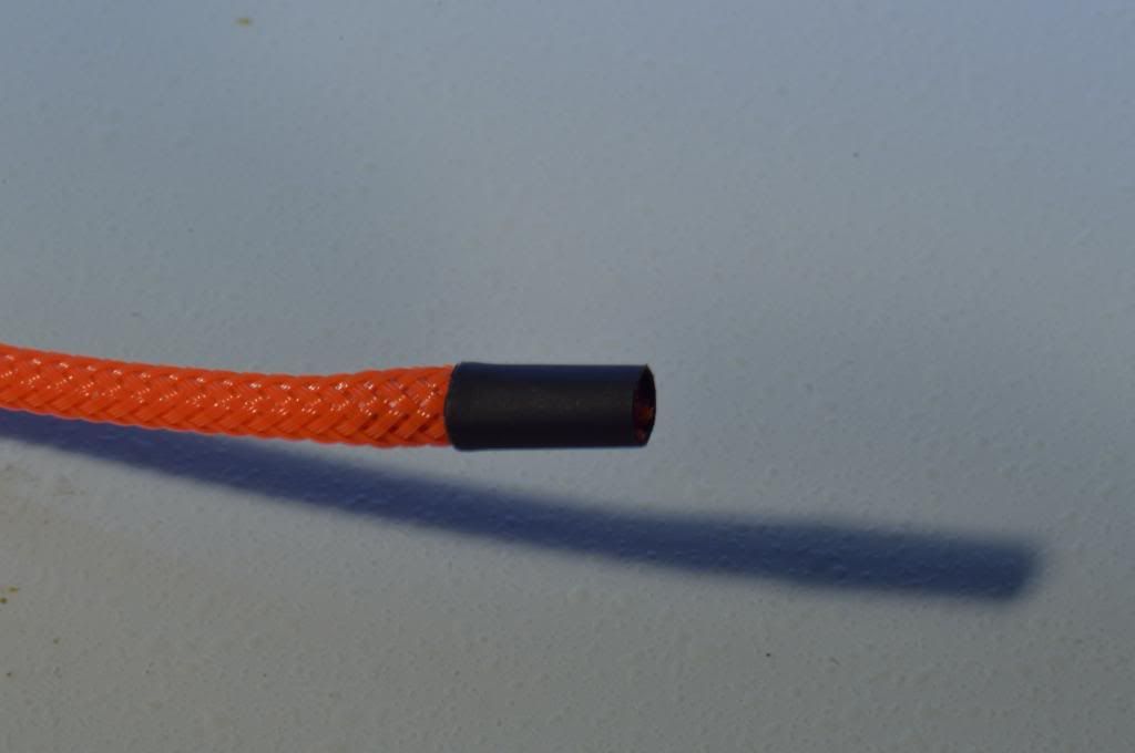
The next step is to cover the crimped connection and the end of the EL wire so it may not short or electroshock you. I used a heat shrink to do this.
WARNING this uses 120V.
At this point you should test the EL wire cable to see if it works and all is well. If it does, then all you have to do is sleeve the EL wire. I used Darkside 2mm(1/8") sleeve from dazmode. You can sleeve it just like you would a regular cable. make sure you leave a little extra at the end.
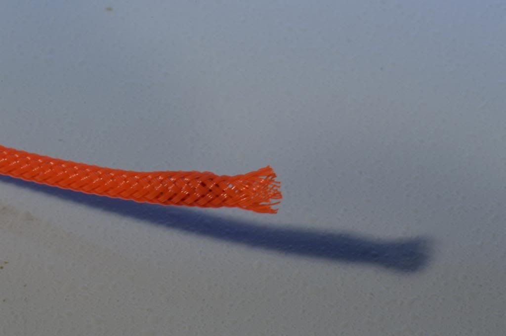
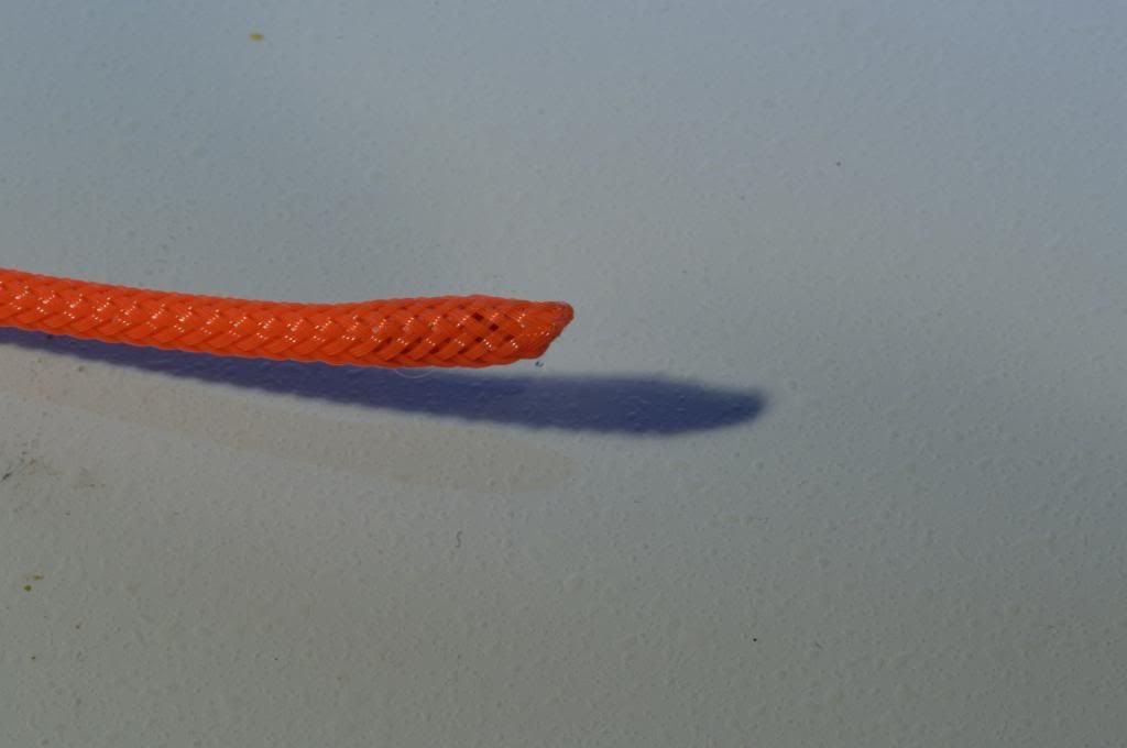
Insert a heat shrink over the extra sleeve as shown below and burn it till the sleeve actually melts (don’t overdo it), this will stop the sleeve from sliding in and out of the wire from this end. The heat shrink is what will compress the sleeve as it is melting. Then wait a few seconds and remove the heat shrink (be careful it's hot)
Next will be to insert the the EL wire (flex neon) onto the feet. You will need to be careful of the orientation you wrap it depending of what corner of the case you will mount the foot on, this will help to neatly hide the feed wires. Feet on one side of the case were rolled counter clockwise and the others clockwise. Make sure you start to roll the EL wire going from the bottom of the feet upward. To keep the wires on the feet I use the type of glue shown below, not quite permanent but definitely does do a good job if applied correctly.
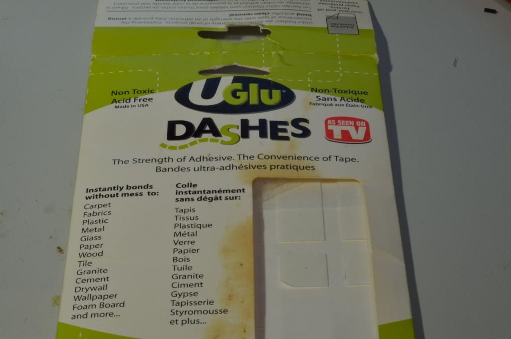
So what I did was I cut little strips using scissors as shown below. Try to match the width of the "cracks" where you will mount the light to avoid putting glue on the exposed portion of the feet. Start with putting the glue at the lowest point of the feet with the end of the EL wire, roll it around the feet nice and tight. Then apply more glue to the last inch as in the picture below.
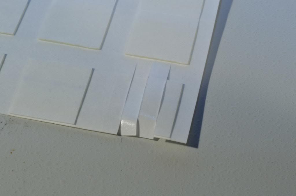
Glue the last part very well as you will be playing around with the feed wire when routing it and it is more prone to being pull or suffer some kind of abuse.
Once this is done all you will have to do is to setup a feed from the power supply to feed the wires. At this moment I am waiting for my inverter so, therefore I am not able to show you that part yet. I did use a splitter to show you all the result
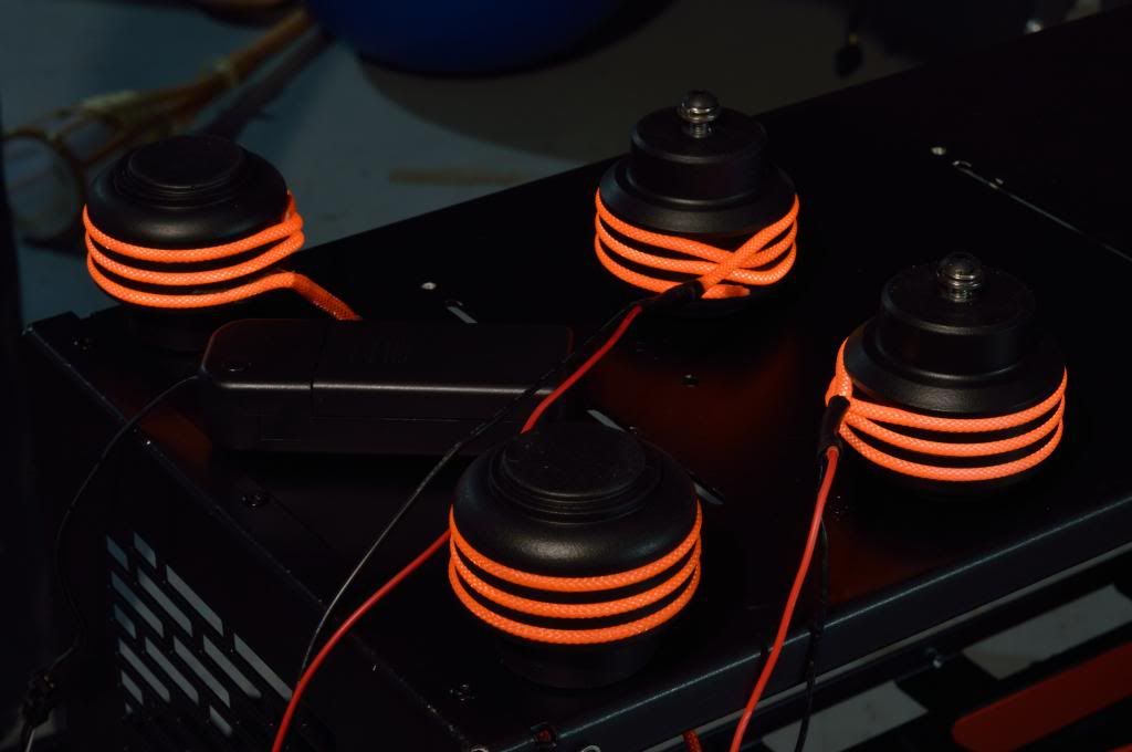
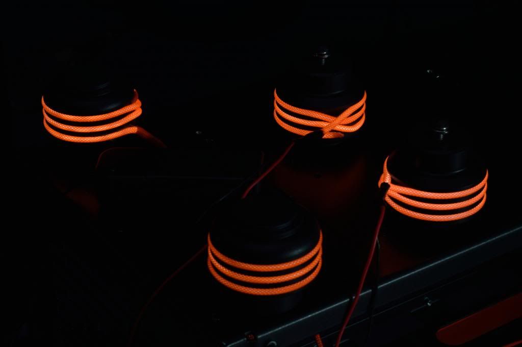
hope you all like it and that it is comprehensive for your use.
Bladepcmods barrel Case feet with sleeved lights.

what you will need
Bladepcmods barrel Case feet

EL Lamp Wire (flex neon)
inverter to convert the 12V voltage from your power supply to the 120V you will need to power the lights (if you buy one for a car on ebay it may already come with this inverter)
wire stripper
wire cutter
solder gun
solder
heat shrink 1/8"
metal crimp and crimper
exacto knife
glue
scissor
2mm(1/8") sleeve. I used darkside sleeve's from dazmode.com they are easy to work with and they look awesome
before we start, I will show you a diagram of how the EL light wire (flex neon) is made and will be making reference to it as we go
First, you will have to strip the EL light much like you would a wire to remove the insulation. As you can see from the picture below, there is a VERY fine copper wire. The EL wire is composed of two copper conductors on the version of the EL light wire feature in the photo and you will have to be careful when striping the wire not to accidently remove them from the light. I found that the doing so with the 18AWG slot you will obtain the best result, although not always perfect

Unfortunately it can accidently happen that the fine copper wire is removed or even that the clear protective sleeve wasn't completely removed. If the clear protective sleeve wasn't removed, you will then need to use the exacto knife to carefully remove the protective sleeve to access the copper wire. Be careful not to cut the copper wire or remove the phosphor coating on the copper core in the process.
In the next step you will need to cut to length the EL wire as required to go around the feet. The bladepcmods feet size I have required 20" but they do make different size of feet, you can do so by rolling it around the feet as shown below. I recommend that you cut an extra inch just in case (you can always cut it to exact length later). Make sure the wire is nice and tight around the feet.

Once you have completed the steps above you should be presented with the result above.

The next step will be to remove the phosphor coating from the end of the copper core so you can properly solder on to the copper core and ensure good contact. You can use the exacto knife or anything that will scratch it off.

Then bend the copper wire back on the top of the colored PVC sleeve as shown below.

At this point I had to prepare the crimper to attach the other feed, I have recycled the metal parts that my ATX pins are attached to when they are sent to me.

You will then need to sit the wire's core onto that colored sleeve and make sure it makes proper contact with the copper wire to transmit the current and then crimp the wire to the EL light wire while always staying on top of the colored sleeve, it is imperative that you do all this over the colored sleeve to avoid any shorts between the copper wire and the copper core.

The next step will then be to solder the copper core to a new wire. I found that the solder I had didn't stick well to the core so I made a hook with the core to help set the wire on it to solder and for extra strength.


Then you will have to put a heat shrink over the copper core and the EL light wire attached together in order to help avoid any possible short.

The next step is to cover the crimped connection and the end of the EL wire so it may not short or electroshock you. I used a heat shrink to do this.

WARNING this uses 120V.
At this point you should test the EL wire cable to see if it works and all is well. If it does, then all you have to do is sleeve the EL wire. I used Darkside 2mm(1/8") sleeve from dazmode. You can sleeve it just like you would a regular cable. make sure you leave a little extra at the end.

Insert a heat shrink over the extra sleeve as shown below and burn it till the sleeve actually melts (don’t overdo it), this will stop the sleeve from sliding in and out of the wire from this end. The heat shrink is what will compress the sleeve as it is melting. Then wait a few seconds and remove the heat shrink (be careful it's hot)


Next will be to insert the the EL wire (flex neon) onto the feet. You will need to be careful of the orientation you wrap it depending of what corner of the case you will mount the foot on, this will help to neatly hide the feed wires. Feet on one side of the case were rolled counter clockwise and the others clockwise. Make sure you start to roll the EL wire going from the bottom of the feet upward. To keep the wires on the feet I use the type of glue shown below, not quite permanent but definitely does do a good job if applied correctly.

So what I did was I cut little strips using scissors as shown below. Try to match the width of the "cracks" where you will mount the light to avoid putting glue on the exposed portion of the feet. Start with putting the glue at the lowest point of the feet with the end of the EL wire, roll it around the feet nice and tight. Then apply more glue to the last inch as in the picture below.


Glue the last part very well as you will be playing around with the feed wire when routing it and it is more prone to being pull or suffer some kind of abuse.
Once this is done all you will have to do is to setup a feed from the power supply to feed the wires. At this moment I am waiting for my inverter so, therefore I am not able to show you that part yet. I did use a splitter to show you all the result


hope you all like it and that it is comprehensive for your use.


Comment